Student Work | Mass STEM Hub
High School | Engineering | IED | Challenge: Manufacturing a Box
March 08, 2021
Check out the student work submitted for real-world industry feedback! Learn more about submitting student work to receive real-world feedback here!
Grade: High School
PLTW Course: IED (Introduction to Engineering Design)
Submission type: Challenge: Manufacturing a Box
Project overview: In the Project Lead The Way (PLTW) Introduction to Engineering Design class, high school students teams apply their learnings about engineering design and manufacturing to design, test, and improve a manufacturing process to build boxes. They create technical sketches and select one that will drive their manufacturing process. As a team they design a process flow diagram and build a prototype. After assessing its quality, they iterate on process and set it up for mass production.
Student submission:

Select judge feedback:
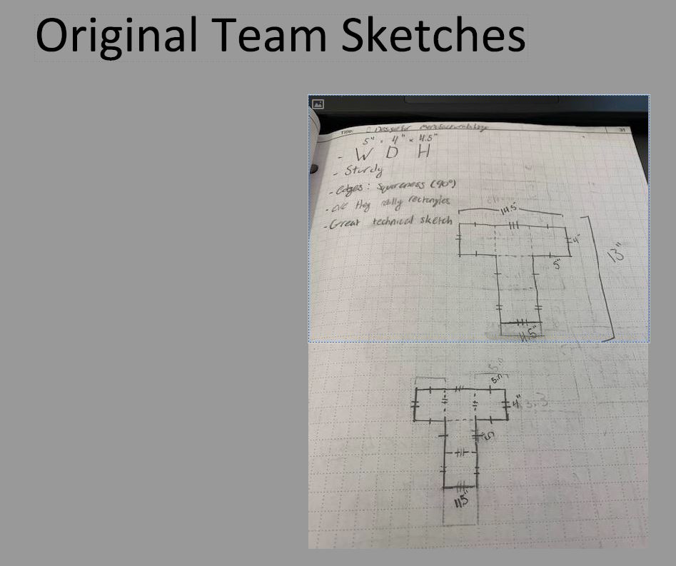
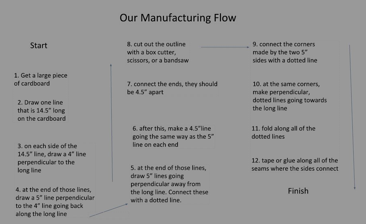
“The technical drawing looks great! You included a lot of information with very little written. I like that you gave overall dimensions so whoever is cutting out this shape knows roughly how big of a piece of cardboard to grab. You could do the math, but in industry it’s best to make things easy and clear for manufacturing. The manufacturing process diagram is a little hard to read because the arrows don’t really connect the steps. Also some of the steps just detail each line drawn on the cardboard, where you could save some steps and just tell the user to draw the flat pattern to scale on the cardboard. Also at the end the instructions say “glue or tape.” In my experience in industry you never want to give a choice in a drawing or a process, you always want to be definitive so later on if there is a problem, you can be sure which method was used. I had an old boss tell me “If you give a choice on a drawing, you’re asking someone else to do your job for you.””
– Associate, Mechanical Engineer, L3 Harris
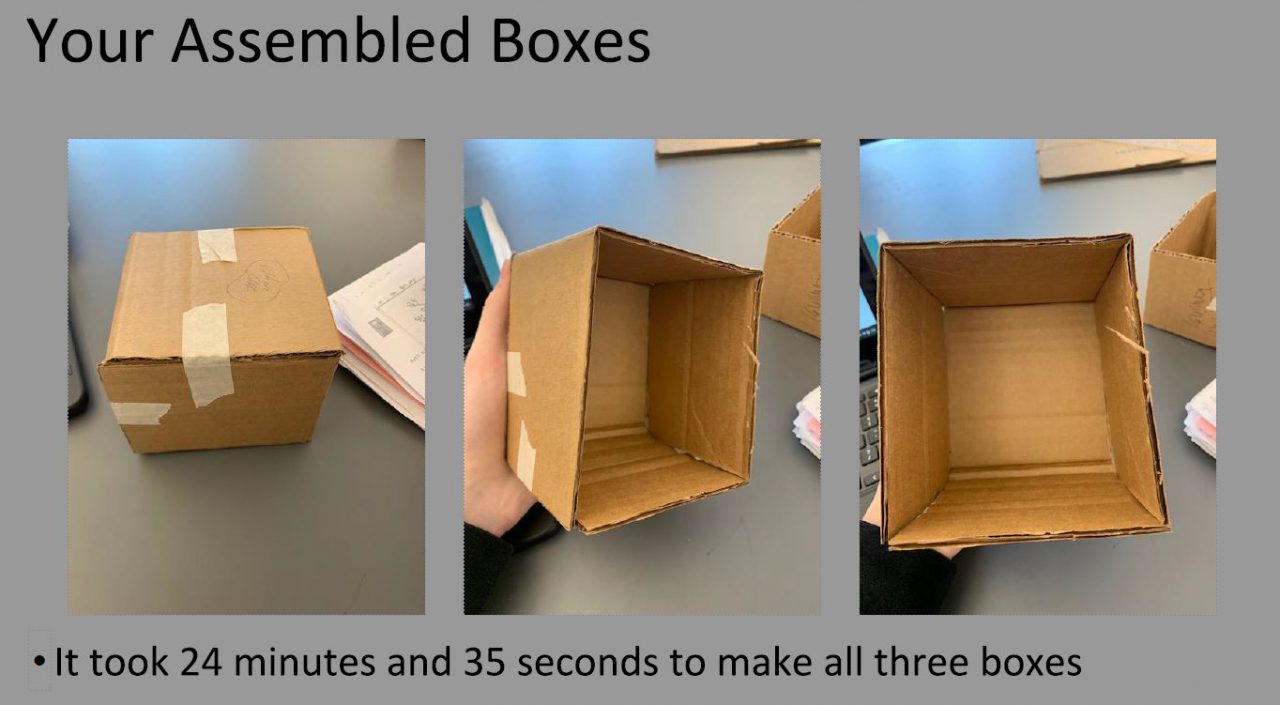
“Awesome work listing the requirements on the tech drawing — very important to do that! Great work with the process flow, the level of detail is perfect and clean and each individual step is easy to follow your prototypes were clean and neat, and your process analysis was a great piece to look into and is a very real world exercise! Interesting to see the parallel lines notation, It is not bad by any means to use, however when drawings start getting complicated they will make it overly busy to the point that it becomes a jumbled mess. In industry they are a rare thing to find on drawings, and in cases such as yours, approximately straight lines are assumed to be straight, approximately 90* angles are assumed to be 90* and parallel lines assumed to be parallel, unless otherwise noted. Be careful of over-constraining drawings, along the length that you have listed as 14.5 you have 2 dimensions in the upper right diagram which is good, but also all you need, when combined with the lower drawing (I am making the assumption it is flipped 180* to approximately match convention) you add a 3rd dimension. This third dimension over-constrains the sketch. Your process flow is awesome, but to go one step further, consider your options and be cleaver… process flows can be made with only a few words per item if you include pictures (which are worth a thousand words each). Your diagram was a bit hard to follow, I think mostly due to it not following standard convention and the arrows being small. Consider moving left to right then down (like how you read) and/or using text blocks with larger arrows could go a long way!”
– Manufacturing Engineer, BAE Systems
Award: User Experience Award (2020-21)
School: Billerica Memorial High School
Teacher: Amy Skrobis